1.在哪里画
在开始学画点和线之前,我们要先想一想,我们的点要画在屏幕上的哪里?我们该如何描述屏幕上的位置?
在上一篇基础中,我们从乐乐大佬抄到了一个模板,其中的顶点/片元着色器是这样的:
|
1 2 3 4 5 6 7 8 9 10 11 12 13 |
//顶点着色器 v2f vert(appdata_base v) { v2f o; o.pos = mul (UNITY_MATRIX_MVP, v.vertex); o.scrPos = ComputeScreenPos(o.pos); return o; } //片元着色器 fixed4 frag(v2f _iParam) : COLOR0 { vec2 fragCoord = gl_FragCoord; return main(gl_FragCoord); } |
其中顶点着色器没什么好说的,就是把模型坐标转换为屏幕坐标。
而片元着色器中的gl_FragCoord则是模板中在上方定义的GLSL的变量:
|
1 2 3 4 |
// 屏幕的尺寸 #define iResolution _ScreenParams // 屏幕中的坐标,以pixel为单位 #define gl_FragCoord ((_iParam.srcPos.xy/_iParam.srcPos.w)*_ScreenParams.xy) |
其中_ScreenParams是Unity内置的屏幕坐标参数,第一条定义只是把它换了个名字而已。
第二条定义中的 (_iParam.srcPos.xy/_iParam.srcPos.w) 是为了 得到在屏幕中归一化后的屏幕位置 ,即返回范围在(0,1)屏幕横纵坐标值。屏幕的左下角值为(0,0),右上角值为(1,1)。然后再乘以屏幕的长宽像素值,就得到了这个片元对应的屏幕像素位置。
几种常见的位置计算:
|
1 2 3 4 5 6 7 8 9 |
vec4 main(vec2 fragCoord) { vec2 pos = fragCoord; // pos.x ~ (0, iResolution.x), pos.y ~ (0, iResolution.y) vec2 pos = fragCoord.xy / iResolution.xy; // pos.x ~ (0, 1), pos.y ~ (0, 1) vec2 pos = fragCoord / min(iResolution.x, iResolution.y); // If iResolution.x > iResolution.y, pos.x ~ (0, 1.xx), pos.y ~ (0, 1) vec2 pos =fragCoord.xy / iResolution.xy * 2. - 1.; // pos.x ~ (-1, 1), pos.y ~ (-1, 1) vec2 pos = (2.0*fragCoord.xy-iResolution.xy)/min(iResolution.x,iResolution.y); // If iResolution.x > iResolution.y, pos.x ~ (-1.xx, 1.xx), pos.y ~ (-1, 1) return vec4(1); } |

其中后面两种计算是将位置映射到了(-1,1)的范围,这样更方便计算。
2.画第一个点(圆)
在shader中,一个点其实也就是一个圆形,那么圆形作为一个基础图形计算起来也不是很难。首先我们在properties里定义两个参数,_Parameters和_Color分别用来描述我们的圆心坐标,圆半径和颜色
|
1 2 3 4 |
Properties{ _Parameters ("Circle Parameters", Vector) = (0.5, 0.5, 10, 0) // Center: (x, y), Radius: z _Color ("Circle Color", Color) = (1, 1, 1, 1) } |
然后在加入一个小小的圆形算法:
|
1 2 3 4 5 6 7 8 |
vec4 circle(vec2 pos, vec2 center, float radius, float4 color) { if (length(pos - center) < radius) { // In the circle return vec4(1, 1, 1, 1) * color; } else { return vec4(0, 0, 0, 1); } } |
函数也很简单,传入一个坐标点pos,一个圆形的中点center,半径radius以及颜色color,计算坐标点与中心点的距离,如果在圆内返回颜色值,圆外返回黑色。
接下来只要在main函数内调用一下这个函数就可以了:
|
1 2 3 |
vec4 main(vec2 fragCoord) { return circle(fragCoord, _Parameters.xy * iResolution.xy, _Parameters.z, _Color); } |
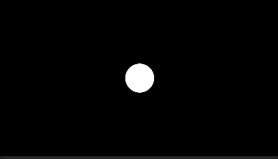
接下来只要稍微调一调坐标就可以得到这样的效果(_Parameters(0.5,0.5,100)):
然后我还发现了一个好玩的现象,我平时开发比较习惯使用2by3格式的布局,这样可以同时看到game窗口与scene窗口,而ShaderToy是基于屏幕绘制的,我在Unity里是通过一个全屏的面板来模拟屏幕绘制的,但是在game的全屏很明显不是scene的全屏,于是就有了这样的效果:
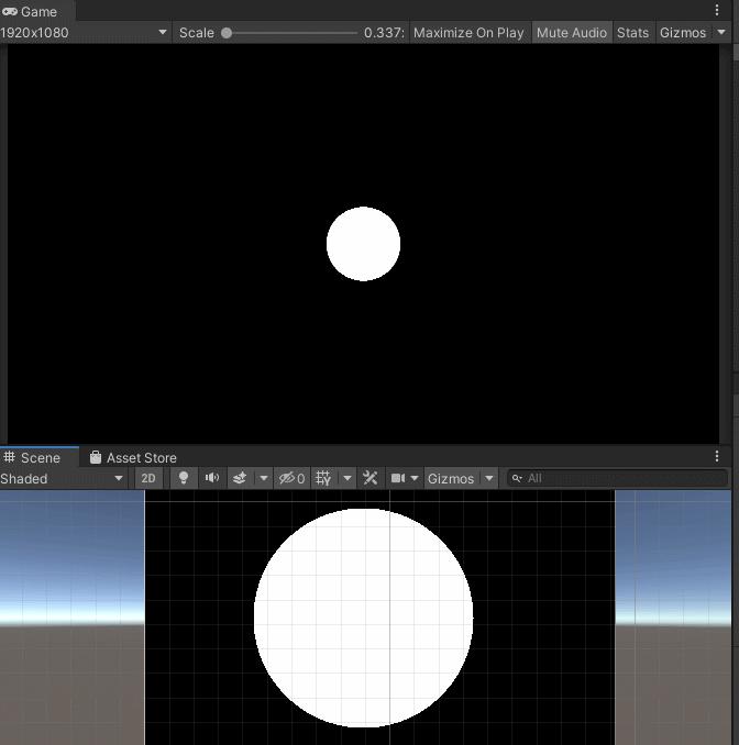
很明显,对于game和scene窗口,他们有各自的范围与尺度(同样是100半径,但是在两个窗口的大小完全不一样,因为game我锁了1920*1080的分辨率)
P.S.圆的抗锯齿
Shader中抗锯齿的原理大概是这样:由于原来非A即B的计算会使得A和B的交界处产生锯齿(例如上面圆的边界),因此我们只需要在A和B的边界平缓过渡即可。这往往需要透明度的配合,即使用透明度来混合颜色。
在shader中,一种常见的抗锯齿(平滑)操作是使用smoothstep函数。smoothstep函数在CG文档里面是这样的:
|
1 2 3 4 5 6 7 |
smoothstep(a,b,x) Interpolates smoothly from 0 to 1 based on x compared to a and b. 1) Returns 0 if x < a < b or x > a > b 1) Returns 1 if x < b < a or x > b > a 3) Returns a value in the range [0,1] for the domain [a,b]. |
他的返回范围总是在(0,1)内,也就是在透明度的范围内~那么接下来我们就可以优化一下我们之前的圆形函数了:
|
1 2 3 4 5 |
vec4 circle(vec2 pos, vec2 center, float radius, float3 color, float antialias) { float d = length(pos - center) - radius; float t = smoothstep(0, antialias, d); return vec4(color, 1.0 - t); } |
antialias就是平滑过渡的边界范围。为了方便调试,我们可以在shader中利用_Parameters的w分量作为抗锯齿因子,当然在实际工程中可以设为定值。
注意这里的_Parameters是刚才我们自己定义的参数的w,可以自己调一调感受一下smoothstep这个函数的神妙之处。
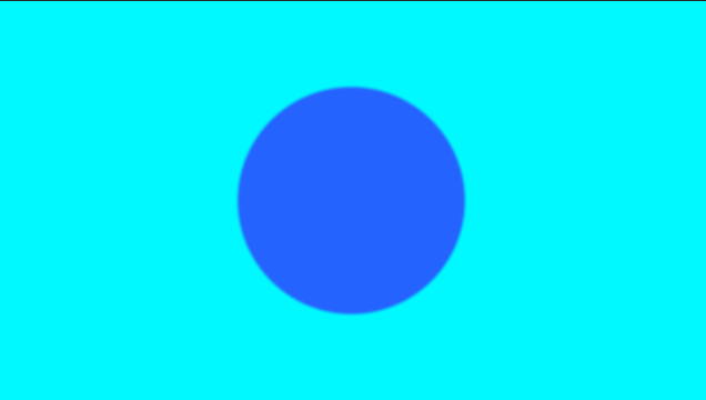
这里的含义其实就是根据点到圆心的距离在减半径的值进行模糊,也就是说在圆内的点,其实d都为负,对应的t都为0,而圆边缘外的范围是我们模糊的范围,antialias也就是我们到底要对圆外多大范围进行模糊。
接下来就是和背景颜色进行混合,我们使用的是lerp函数(在ShaderToy中对应的是mix函数):
|
1 2 3 4 5 6 7 8 |
vec4 main(vec2 fragCoord) { vec2 pos = fragCoord; // pos.x ~ (0, iResolution.x), pos.y ~ (0, iResolution.y) vec4 layer1 = vec4(_BackgroundColor.rgb, 1.0); vec4 layer2 = circle(pos, _Parameters.xy * iResolution.xy, _Parameters.z, _CircleColor.rgb, _Parameters.w); return mix(layer1, layer2, layer2.a); } |
|
1 2 3 4 5 6 7 8 9 10 11 12 13 14 15 16 17 18 19 20 21 22 23 24 25 26 27 28 29 30 31 32 33 34 35 36 37 38 39 40 41 42 43 44 45 46 47 48 49 50 51 52 53 54 55 56 57 58 59 60 61 62 63 64 65 66 67 |
Shader "Shadertoy/Point" { Properties{ _Parameters("Circle Parameters", Vector) = (0.5, 0.5, 10, 0) // Center: (x, y), Radius: z _Color("Circle Color", Color) = (1, 1, 1, 1) _BackgroundColor("Background Color", Color) = (1, 1, 1, 1) } CGINCLUDE #include "UnityCG.cginc" #pragma target 3.0 #define vec2 float2 #define vec3 float3 #define vec4 float4 #define mat2 float2x2 #define mat3 float3x3 #define mat4 float4x4 #define iGlobalTime _Time.y #define mod fmod #define mix lerp #define fract frac #define texture2D tex2D #define iResolution _ScreenParams #define gl_FragCoord ((_iParam.scrPos.xy/_iParam.scrPos.w) * _ScreenParams.xy) #define PI2 6.28318530718 #define pi 3.14159265358979 #define halfpi (pi * 0.5) #define oneoverpi (1.0 / pi) fixed4 _Parameters; fixed4 _Color; fixed4 _BackgroundColor; struct v2f { float4 pos : SV_POSITION; float4 scrPos : TEXCOORD0; }; v2f vert(appdata_base v) { v2f o; o.pos = UnityObjectToClipPos(v.vertex); o.scrPos = ComputeScreenPos(o.pos); return o; } vec4 main(vec2 fragCoord); fixed4 frag(v2f _iParam) : COLOR0{ vec2 fragCoord = gl_FragCoord; return main(gl_FragCoord); } vec4 circle(vec2 pos, vec2 center, float radius, float3 color, float antialias) { float d = length(pos - center) - radius; float t = smoothstep(0, antialias, d); return vec4(color, 1.0 - t); } vec4 main(vec2 fragCoord) { vec4 layer1 = vec4(_BackgroundColor.rgb, 1.0); vec4 layer2 = circle(fragCoord, _Parameters.xy * iResolution.xy, _Parameters.z, _Color.rgb, _Parameters.w); return mix(layer1, layer2, layer2.a); } ENDCG SubShader{ Pass { CGPROGRAM #pragma vertex vert #pragma fragment frag #pragma fragmentoption ARB_precision_hint_fastest ENDCG } } FallBack Off } |
3.画两个点
之前的circle函数已经可以画出任何一个大小、圆心的圆了,现在的问题仅仅是如何将这些元素都添加到画布上。一种基本的思想就是图层叠加,这很像我们在Photoshop中做的事情:背景在最后一层,我们只需要增加新的图层,并确保它们按层级顺序一层层向上排列即可。所以,我们可以这样做:
|
1 2 3 4 5 6 7 8 9 10 11 12 13 14 |
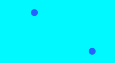
vec4 main(vec2 fragCoord) { vec4 layer1 = vec4(_BackgroundColor.rgb, 1.0); vec2 point1 = vec2(0.3, 0.8); vec2 point2 = vec2(0.8, 0.2); vec4 layer2 = circle(fragCoord, point1 * iResolution.xy, _Parameters.z, _Color.rgb, _Parameters.w); vec4 layer3 = circle(fragCoord, point2 * iResolution.xy, _Parameters.z, _Color.rgb, _Parameters.w); vec4 fragColor = mix(layer1, layer2, layer2.a); fragColor = mix(fragColor, layer3, layer3.a); return fragColor; } |
上面的代码中,我们绘制了两个圆,一个圆心位置在(0.3, 0.8)处,一个在(0.8, 0.2)处。 layer1仍旧是背景层, layer2和 layer1分别表示两个圆所在图层。我们按照层级顺序依次调用 lerp函数(也就是代码中的mix函数)即可以混合这些元素。
4.画一条线
和上面的画圆操作一样,只不过画线要计算的是片元是否处于这条线上,同样,线也需要具有一定的宽度:
|
1 2 3 4 5 6 7 8 |
vec4 line(vec2 pos, vec2 point1, vec2 point2, float width, float3 color, float antialias) { float k = (point1.y - point2.y)/(point1.x - point2.x); float b = point1.y - k * point1.x; float d = abs(k * pos.x - pos.y + b) / sqrt(k * k + 1); float t = smoothstep(width/2.0, width/2.0 + antialias, d); return vec4(color, 1.0 - t); } |
其中两点确定一条支线的公式大家应该还都记得,y=kx+b,在计算完直线方程后,接下来就要计算点到直线的距离d了。想必大家应该都已经忘了点到直线距离公式:
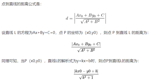
说实话我也两眼一抹黑,甚至还想自己推导一遍这个公式,但是算了半天也没算明白。后面有时间再研究一下吧。
然后在对直线宽度一半进行一次模糊操作去掉锯齿。这里的smoothstep和上面圆形的时候不太一样,不过这里的意思也是当d小于width/2时则返回0,保证这个片元在直线内。
接下来就是在刚才的两个点的基础上,再加一层线的绘制叠加就行了!

完整代码(这里我用传入参数的x作为线的宽度了,因为有点懒不想再新开字段了):
|
1 2 3 4 5 6 7 8 9 10 11 12 13 14 15 16 17 18 19 20 21 22 23 24 25 26 27 28 29 30 31 32 33 34 35 36 37 38 39 40 41 42 43 44 45 46 47 48 49 50 51 52 53 54 55 56 57 58 59 60 61 62 63 64 65 66 67 68 69 70 71 72 73 74 75 76 77 78 79 80 81 |
Shader "Shadertoy/Point" { Properties{ _Parameters("Circle Parameters", Vector) = (0.5, 0.5, 10, 0) // Center: (x, y), Radius: z _Color("Circle Color", Color) = (1, 1, 1, 1) _BackgroundColor("Background Color", Color) = (1, 1, 1, 1) } CGINCLUDE #include "UnityCG.cginc" #pragma target 3.0 #define vec2 float2 #define vec3 float3 #define vec4 float4 #define mat2 float2x2 #define mat3 float3x3 #define mat4 float4x4 #define iGlobalTime _Time.y #define mod fmod #define mix lerp #define fract frac #define texture2D tex2D #define iResolution _ScreenParams #define gl_FragCoord ((_iParam.scrPos.xy/_iParam.scrPos.w) * _ScreenParams.xy) #define PI2 6.28318530718 #define pi 3.14159265358979 #define halfpi (pi * 0.5) #define oneoverpi (1.0 / pi) fixed4 _Parameters; fixed4 _Color; fixed4 _BackgroundColor; struct v2f { float4 pos : SV_POSITION; float4 scrPos : TEXCOORD0; }; v2f vert(appdata_base v) { v2f o; o.pos = UnityObjectToClipPos(v.vertex); o.scrPos = ComputeScreenPos(o.pos); return o; } vec4 main(vec2 fragCoord); fixed4 frag(v2f _iParam) : COLOR0{ vec2 fragCoord = gl_FragCoord; return main(gl_FragCoord); } vec4 circle(vec2 pos, vec2 center, float radius, float3 color, float antialias) { float d = length(pos - center) - radius; float t = smoothstep(0, antialias, d); return vec4(color, 1.0 - t); } vec4 drawLine(vec2 pos, vec2 point1, vec2 point2, float width, float3 color, float antialias) { float k = (point1.y - point2.y) / (point1.x - point2.x); float b = point1.y - k * point1.x; float d = abs(k * pos.x - pos.y + b) / sqrt(k * k + 1); float t = smoothstep(width / 2.0, width / 2.0 + antialias, d); return vec4(color, 1.0 - t); } vec4 main(vec2 fragCoord) { vec4 layer1 = vec4(_BackgroundColor.rgb, 1.0); fixed2 point1 = fixed2(0.3, 0.8) * iResolution.xy; fixed2 point2 = fixed2(0.8, 0.2) * iResolution.xy; vec4 layer2 = drawLine(fragCoord, point1, point2, _Parameters.x, _Color.rgb, _Parameters.w); vec4 layer3 = circle(fragCoord, point1, _Parameters.z, _Color.rgb, _Parameters.w); vec4 layer4 = circle(fragCoord, point2, _Parameters.z, _Color.rgb, _Parameters.w); fixed4 fragColor = mix(layer1, layer2, layer2.a); fragColor = mix(fragColor, layer3, layer3.a); fragColor = mix(fragColor, layer4, layer4.a); return fragColor; } ENDCG SubShader{ Pass { CGPROGRAM #pragma vertex vert #pragma fragment frag #pragma fragmentoption ARB_precision_hint_fastest ENDCG } } FallBack Off } |
